Kinematics
Concepts and Principles
Rotation about a Fixed Axis (Spinning)
Imagine a rigid body constrained to rotate about a fixed axis. Non-physicists would say that the object is spinning.
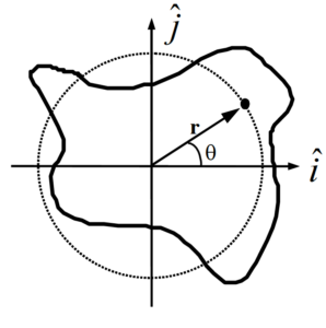 |
Place the origin of a coordinate system at the location of the rotation axis. Examine an arbitrary point on the object, denoted by the position vector
or
Notice that as the object spins, this point undergoes circular motion (denoted by the dashed line). Although the actual object may be of irregular shape, as it spins every point on the object undergoes circular motion. Moreover, since each and every point on the object has to complete an entire cycle around the rotation axis in the same amount of time, every point must undergo circular motion with the same angular speed (w(t)) and the same angular acceleration (a(t)). |
Since every point on a rigid body must have the same angular speed and the same angular acceleration, we will speak of the angular speed and angular acceleration of the object, rather than the angular speed and angular acceleration of some point on the object.
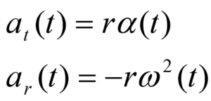
Given that every point on a spinning object undergoes circular motion, the results from our study of circular motion will be very important in analyzing spinning objects. Recall that with q(t) defined as the angular position of an arbitrary point on the rigid-body,
and
Moreover, the velocity and acceleration of any point on a spinning, rigid body can be related to the angular quantities:
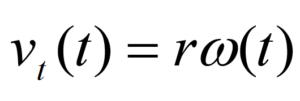
and
Rotation and Translation
To describe the motion of an object undergoing pure rotation (spinning), we have to describe the circular motion each point on the object undergoes. What must we do if the object is simultaneously rotating and translating (moving in a plane perpendicular to the rotation axis), like a wheel rolling down an incline?
The answer lies in the independence of these two types of motion. In much the same manner as we attacked kinematics in two dimensions by independently analyzing the horizontal and vertical motions, we will attack rigid-body kinematics by independently analyzing the rotational and translational motions. In short, we will model any motion of a rigid-body as a superposition of a translation of the object’s center-of-mass (CM) (which we will analyze by particle kinematics) and a rotation about an axis passing through the CM (which we will analyze by the kinematics of spinning, detailed above).
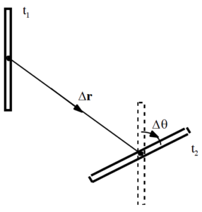 |
For example, examine the motion of the thin rod between t1 and t2. Although the rod may have been spinning crazily through space between these two times, we can model its motion as a superposition of a simple translation of its CM without rotation (denoted by the vector Dr), which leaves the rod in the orientation denoted by the dashed lines, and a simple rotation about an axis through its CM without translation (denoted by Dq), which leaves the rod in its proper, final orientation. If we imagine the time difference (t2 – t1) shrinking toward zero, hopefully it becomes plausible that we can model any motion through this method. |
In summary, to describe the motion of an arbitrary rigid body we will break the motion down into a pure translation of the CM and a pure rotation about the CM. We will use particle kinematics to describe the translational portion of the motion and the kinematics of circular motion to describe the rotational portion. The velocity (or acceleration) of any point on the object is then determined by the sum of the velocity (or acceleration) due to the translation and the velocity (or acceleration) due to the rotation.
Analysis Tools
Pure Rotation
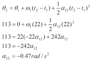
After the off button is pressed, a ceiling fan takes 22 s to come to rest. During this time, it completes 18 complete revolutions.
To analyze this situation, we should first carefully determine and define the sequence of events that take place. At each of these instants, let’s tabulate what we know about the motion. Since we are dealing with pure rotation, the relevant kinematic variables are the angular position, velocity, and acceleration of the fan. Also, let’s take the direction that the fan is initially rotating to be the positive direction.
| Event 1: The ‘off’ button is pressed
t1 = 0 s q1 = 0 rad w1 = a1 = |
Event 2: The ceiling fan stops
t2 = 22 s q2 = 18 (2p) = 113 rad w2 = 0 rad/s a2 = |
Since no specific information concerning the angular acceleration of the fan is given, let’s assume the angular acceleration is constant. (Thus, a1 = a2 = a12.) Since the relationships between angular position, velocity, and acceleration are the same as the relationships between linear position, velocity and acceleration, the kinematic equations for constant linear acceleration must have direct analogies for constant angular acceleration. Thus,
| Now substitute this expression into the other equation:
|
Substitute this result back into the original equation:
|
Notice that the sign of the angular acceleration is negative. This indicates that the angular acceleration is in the opposite direction of the angular velocity, as it should be since the fan is slowing down.
Connecting Pure Rotation to Pure Translation
|
The device at right is used to lift a heavy load. The free rope is attached to a truck which accelerates from rest at a rate of 1.5 m/s2. The inner radius of the pulley is 20 cm and the outer radius is 40 cm. The load must be raised 15 m. |
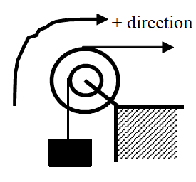 |
The coordinate system chosen indicates that the block moving upward, the pulley rotating clockwise, and the truck moving to the right are all positive.
There are three different objects that we should be able to describe kinematically; the truck, the pulley, and the block. Let’s tabulate everything we know about each object:
| Truck
Event 1: Truck begins to move
t1 = 0 s
r1 = 0 m
v1 = 0 m/s
a1 = 1.5 m/s2
|
Event 2: Block raised 15 m
t2 =
r2 =
v2 =
a2 = 1.5 m/s2
|
Pulley
Event 1: Truck begins to move
t1 = 0 s
q1 = 0 rad
w1 = 0 rad/s
a1 = |
Event 2: Block raised 15 m
t2 =
q2 =
w2 =
a2 = |
Block
Event 1: Truck begins to move
t1 = 0 s
r1 = 0 m
v1 = 0 m/s
a1 =
|
Event 2: Block raised 15 m
t2 =
r2 = 15 m
v2 =
a2 = |
The truck and block exhibit translational motion, so we only have to tabulate linear variables. The pulley spins, so the relevant variables are the angular variables. Notice that just because the block moves 15 m doesn’t mean the truck moves 15 m. Also, the acceleration of the block is not equal to the acceleration of the truck. However, these variables are related to each other since both objects are attached to the same pulley.
Also notice that we can’t currently solve this problem. Each of the objects has three unknown quantities. However, since the kinematics of the three objects are related, we will be able to solve the problem once we’ve worked out the exact relationship between each object’s kinematics.
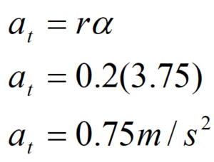
Let’s start with the acceleration. Assuming the rope from the truck does not slip on the pulley, the point on the pulley in contact with the rope must be accelerating at the same rate as the truck. Notice that this acceleration is tangent to the pulley, and this rope is located 0.4 m from the center of the pulley. Therefore, from
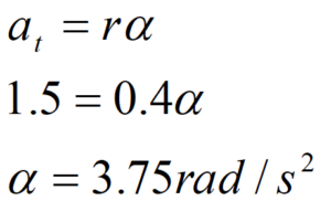
The pulley must have an angular acceleration of 3.75 rad/s2 since it is attached to the truck.
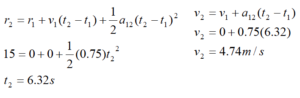
In addition, assuming the rope from the block does not slip on the pulley, the point on the pulley in contact with this rope must be accelerating at:
Since the point on the pulley attached to the block is accelerating at 0.75 m/s2, the block itself must be accelerating at 0.75 m/s2. In a nutshell, what we’ve done is used the acceleration of the truck to find the angular acceleration of the pulley, and then used the angular acceleration of the pulley to find the acceleration of the block. This chain of reasoning is very common.
Now that we know the block’s acceleration, we can solve the problem. Applying the two kinematic equations to the block yields:
Now that we know the final speed of the block, we can find the final angular speed of the pulley and the final speed of the truck:
Again assuming the rope from the block does not slip on the pulley, the point on the pulley in contact with the rope must be moving at the same rate as the block. Notice that this velocity is tangent to the pulley, and this rope is located 0.2 m from the center of the pulley. Therefore, from
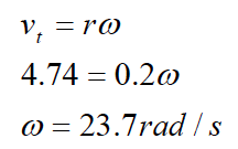
The pulley must have an angular velocity of 23.7 rad/s since it is attached to the block.
In addition, assuming the rope from the truck does not slip on the pulley, the point on the pulley in contact with this rope must be moving at:
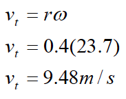
The truck is moving at 9.48 m/s when the block reaches 15 m.
We can relate the displacement of the block to the angular displacement of the pulley and the displacement of the truck using
![]()
where s is (technically) the arc length over which a rope is wrapped around the pulley and q is the angular displacement of the pulley. Of course, the amount of rope wrapped around a pulley is exactly equal to the displacement of the object attached to the rope. Therefore, relating the block to the pulley yields
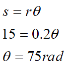
The pulley must have turned through 75 rad since it is attached to the block.
Relating the pulley to the truck results in:
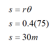
The truck moved 30 m while the block moved 15 m.
Notice that in all cases, the values of the kinematic variables for the truck are exactly twice the values for the block. This is not a coincidence. Since the truck is attached to the pulley at twice the distance from the axle that the block is attached, all of its kinematic variables will have twice the value. Once you understand why this is the case, you can use this insight to simplify your analysis.
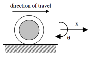
Rotating and Translating
Accelerating from rest, a Cadillac Sedan de Ville can reach a speed of 25 m/s in a time of 6.2 s. During this acceleration, the Cadillac’s tires do not slip in their contact with the road. The diameter of the Cadillac’s tires is 0.80 m.
Let’s examine the motion of one of the Cadillac’s tires. Obviously, the tire both translates and rotates. We will imagine the motion to be a superposition of a pure translation of the CM of the tire and a pure rotation about the CM of the tire.
To analyze the situation, we should define the sequence of events that take place and tabulate what we know about the motion at each event. Since we are dealing with translation as well as rotation, we will need to keep track of both the linear kinematic variables and the angular kinematic variables.
Let’s take the positive x direction to be the direction that the Cadillac translates and the positive q direction to be the direction in which the tires rotate.
| Event 1: The Cadillac begins to accelerate
t1 = 0 s
r1 = 0 m q1 = 0 rad
v1 = 0 m/s w1 = 0 rad/s
a1 = a1 = |
Event 2: The Cadillac reaches 25 m/s
t2 = 6.2 s
r2 = q2 =
v2 = 25 m/s w2 =
a2 = a2 = |
First, let’s examine the translational portion of the tire’s motion.
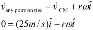
What about the rotational kinematics of the tire? The motion of the tire is the superposition of the pure translational motion of the CM and the pure rotational motion about the CM[1]. Thus, the velocity of any point on the tire is given by
where r is the distance between the point of interest and the rotation axis, i.e., the distance from the CM.
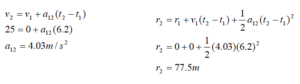
The key insight into studying the rotation of the tire is to realize that at any instant the velocity of the point on the tire in contact with the road is zero because the tire never slips in its contact with the road. Thus, if the CM of the tire is moving forward at
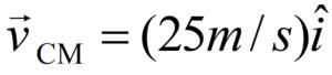
the point on the bottom of the tire must be moving backward relative to the CM at the exact same speed in order for its velocity relative to the ground to be zero! Thus, only a very particular value for w will allow the tire to roll without slipping.
From above,
At the bottom of the tire, , since motion tangent to the tire at the bottom of the tire is motion to the left. Thus,
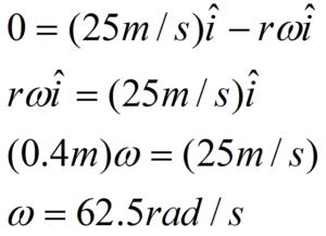
Therefore, at the end of the acceleration, the tire has an angular speed of 62.5 rad/s.
I included all of the vector notation to ensure I did the calculation correctly, but hopefully we can understand the result without getting bogged down in notation. Basically, the bottom of the tire can’t be moving relative to the ground if the wheel rolls without slipping. Since the CM of the tire is moving forward at 25 m/s, the bottom of the tire must be moving backward at 25 m/s relative to the CM. From the CM frame of reference, the tire is just spinning, and I can apply v = r w to calculate the angular speed of the tire.
We can find the angular acceleration and angular position of the tire by using the linear variables determined above and the method described in the previous example, or by using the equations for constant angular acceleration.
Thus, the wheel rotates through 194 rad, or 30.8 revolutions, while accelerating.
Activities

A girl pedals her bicycle, from rest, at a constantly increasing speed along a level path. Examine the motion of a point on the rim of her tire and a point midway along a spoke for one complete cycle, starting from rest. Set the origin of the coordinate system at the center of the tire.
| a. Using polar coordinates, sketch position, velocity, and acceleration vs. time graphs for each point. |
| b. Sketch angular position, angular velocity, and angular acceleration vs. time graphs for each point. |
| A block is attached to a rope that is wound around a pulley. Sketch velocity vs. time and acceleration vs. time graphs for a point on the rim of the pulley and for the block. Set the origin of the coordinate system at the center of the pulley. | 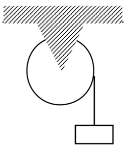 |
a. Sketch the polar components of the point on the rim’s motion and the Cartesian components of the block’s motion when the block is lowered at constant speed.
b. Sketch the polar components of the point on the rim’s motion and the Cartesian components of the block’s motion when the block is released from rest.
| The two wheels at right are coupled together by an elastic conveyor belt that does not slip on either wheel. Examine the motion of a point on the rim of the large wheel and a point on the rim of the small wheel when the conveyor belt’s speed increases from rest. Set the origin of a coordinate system at the center of each pulley. | 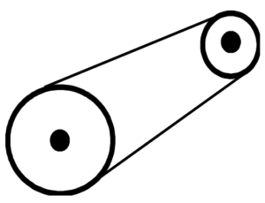 |
| a. Using polar components, sketch velocity and acceleration vs. time graphs for each point. |
| b. Sketch angular velocity and angular acceleration vs. time graphs for each point. |
| The two gears at right have equal teeth spacing and are well-meshed. Examine the motion of a point on the rim of the large gear and a point on the rim of the small gear when the small gear’s speed increases from rest in the counterclockwise direction. Set the origin of a coordinate system at the center of each gear and let counterclockwise be the positive direction. | 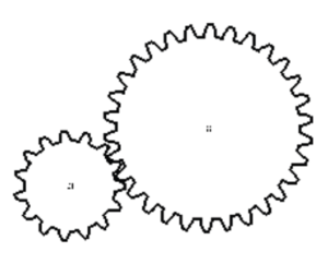 |
| a. Using polar components, sketch velocity and acceleration vs. time graphs for each point. |
| b. Sketch angular velocity and angular acceleration vs. time graphs for each point. |
Below are angular position vs. time graphs for six different objects.
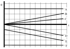
Rank these graphs on the basis of the angular velocity of the object.
Largest Positive 1. _____ 2. _____ 3. _____ 4. _____ 5. _____ 6. _____ Largest Negative
_____ The ranking cannot be determined based on the information provided.
Explain the reason for your ranking:
Rank these graphs on the basis of the angular acceleration of the object.
Largest Positive 1. _____ 2. _____ 3. _____ 4. _____ 5. _____ 6. _____ Largest Negative
_____ The ranking cannot be determined based on the information provided.
Explain the reason for your ranking:
Below are angular velocity vs. time graphs for six different objects.
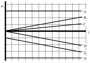
Rank these graphs on the basis of the angular acceleration of the object.
Largest Positive 1. _____ 2. _____ 3. _____ 4. _____ 5. _____ 6. _____ Largest Negative
_____ The ranking cannot be determined based on the information provided.
Explain the reason for your ranking:
Rank these graphs on the basis of the angular displacement of the object over the time interval shown.
Largest Positive 1. _____ 2. _____ 3. _____ 4. _____ 5. _____ 6. _____ Largest Negative
_____ The ranking cannot be determined based on the information provided.
Explain the reason for your ranking:
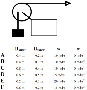
The pulley below has the outer radius and inner radius indicated. In all cases, the horizontal rope is pulled to the right at the same, constant speed.
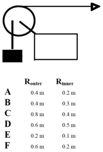
Rank these scenarios on the basis of the angular speed of the pulley.
Largest 1. _____ 2. _____ 3. _____ 4. _____ 5. _____ 6. _____ Smallest
_____ The ranking cannot be determined based on the information provided.
Explain the reason for your ranking:
Rank these scenarios on the basis of the speed of the block.
Largest 1. _____ 2. _____ 3. _____ 4. _____ 5. _____ 6. _____ Smallest
_____ The ranking cannot be determined based on the information provided.
Explain the reason for your ranking:
The two wheels, with radii indicated below, are linked together by an elastic conveyor belt that does not slip on either wheel. In all cases, the small wheel is turning at the same, constant angular speed.
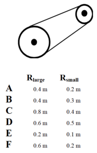
Rank the scenarios on the basis of the speed of the belt.
Largest 1. _____ 2. _____ 3. _____ 4. _____ 5. _____ 6. _____ Smallest
_____ The ranking cannot be determined based on the information provided.
Explain the reason for your ranking:
Rank the scenarios on the basis of the angular speed of the large wheel.
Largest 1. _____ 2. _____ 3. _____ 4. _____ 5. _____ 6. _____ Smallest
_____ The ranking cannot be determined based on the information provided.
Explain the reason for your ranking:
The two gears, with radii indicated below, have equal teeth spacing and are well-meshed. In all cases, the large gear is turning at the same, constant angular speed.
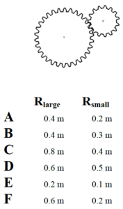
Rank the scenarios on the basis of the speed of the teeth on the small gear.
Largest 1. _____ 2. _____ 3. _____ 4. _____ 5. _____ 6. _____ Smallest
_____ The ranking cannot be determined based on the information provided.
Explain the reason for your ranking:
Rank the scenarios on the basis of the angular speed of the small gear.
Largest 1. _____ 2. _____ 3. _____ 4. _____ 5. _____ 6. _____ Smallest
_____ The ranking cannot be determined based on the information provided.
Explain the reason for your ranking:
A pulley system is illustrated below. The horizontal rope is pulled to the right at constant speed. Each letter designates a point on either the pulley or on one of the two ropes. Neither rope slips in its contact with the pulley.
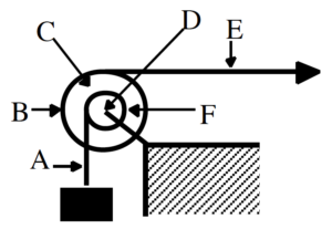
Rank the designated points on the basis of their speed.
Largest 1. _____ 2. _____ 3. _____ 4. _____ 5. _____ 6. _____ Smallest
_____ The ranking cannot be determined based on the information provided.
Explain the reason for your ranking:
Rank the designated points on the basis of the magnitude of their acceleration.
Largest 1. _____ 2. _____ 3. _____ 4. _____ 5. _____ 6. _____ Smallest
_____ The ranking cannot be determined based on the information provided.
Explain the reason for your ranking:
At the instant shown, the pulley below has the outer radius, inner radius, angular velocity, and angular acceleration indicated. Positive angular quantities are counterclockwise.
Rank these scenarios on the basis of the speed of the block.
Largest 1. _____ 2. _____ 3. _____ 4. _____ 5. _____ 6. _____ Smallest
_____ The ranking cannot be determined based on the information provided.
Explain the reason for your ranking:
Rank these scenarios on the basis of the magnitude of the acceleration of the block.
Largest 1. _____ 2. _____ 3. _____ 4. _____ 5. _____ 6. _____ Smallest
_____ The ranking cannot be determined based on the information provided.
Explain the reason for your ranking:
At the instant shown, the pulley below has the outer radius, inner radius, angular velocity, and angular acceleration indicated. Positive angular quantities are counterclockwise.
Rank these scenarios on the basis of the magnitude of the acceleration of a point on the inner rim of the pulley.
Largest 1. _____ 2. _____ 3. _____ 4. _____ 5. _____ 6. _____ Smallest
_____ The ranking cannot be determined based on the information provided.
Explain the reason for your ranking:
Rank these scenarios on the basis of the magnitude of the acceleration of the block.
Largest 1. _____ 2. _____ 3. _____ 4. _____ 5. _____ 6. _____ Smallest
_____ The ranking cannot be determined based on the information provided.
Explain the reason for your ranking:
After being turned on, a record player (an antique device used by hipsters to listen to music) reaches its rated angular speed of 45 rpm (4.71 rad/s) in 1.5 s.
Motion Information
| Event 1:
t1 =
q1 =
w1 =
a1 = |
Event 2:
t2 =
q2 =
w2 =
a2 = |
Mathematical Analysis[i]
A clothes dryer spins clothes at an angular speed of 6.8 rad/s. Starting from rest, the drier reaches its operating speed with an average angular acceleration of 7.0 rad/s2.
Motion Information
| Event 1:
t1 =
q1 =
w1 =
a1 = |
Event 2:
t2 =
q2 =
w2 =
a2 = |
Mathematical Analysis[ii]
In a secret Las Vegas research laboratory, two roulette wheels (Aladdin’s and Bally’s) are undergoing extensive testing. Both wheels are spun at 25 rad/s. After 6.4 s, both wheels have rotated through 100 rad. However, the angular speed of Aladdin’s wheel decreases as a linear function of time while the angular speed of Bally’s wheel decreases as an exponential function of time, w = Ae-Bt.
Motion Graph Motion Information
| Aladdin’s Wheel
Event 1:
t1 =
q1 =
w1 =
a1 = |
Event 2:
t2 =
q2 =
w2 =
a2 = |
Bally’s Wheel
Event 1:
t1 =
q1 =
w1 =
a1 = |
Event 2:
t2 =
q2 =
w2 =
a2 = |
Question
Based only on the graph, which roulette wheel is spinning faster after 6.4s? Explain.
Mathematical Analysis[iii]
A diver rotating at approximately constant angular velocity completes four revolutions before hitting the water. She jumped vertically upward with an initial velocity of 5 m/s from a diving board 4 m above the water.
Motion Information
| Event 1:
t1 =
r1 = q1 =
v1 = w1 =
a1 = a1 = |
Event 2:
t2 =
r2 = q2 =
v2 = w2 =
a2 = a2 = |
Mathematical Analysis[iv]
A baton twirler throws a spinning baton directly upward. As it goes up and returns to the twirler’s hand, it turns through four complete revolutions. The constant angular speed of the baton while in the air is 10 rad/s.
Motion Information
| Event 1:
t1 =
r1 = q1 =
v1 = w1 =
a1 = a1 = |
Event 2:
t2 =
r2 = q2 =
v2 = w2 =
a2 = a2 = |
Mathematical Analysis[v]
A quarterback throws a pass that is a perfect spiral, spinning at 50 rad/s. The ball is thrown at 19 m/s at an angle of 350 above the horizontal. The ball leaves the quarterback’s hand 2.0 m above the Astroturf and is caught just before it hits the turf. (The opposing coach thinks the ball was trapped. We are still waiting for the result of the challenge.)
Motion Information
| Event 1:
t1 =
r1x = r1y = q1 =
v1x = v1y = w1 =
a1x = a1y = a1 = |
Event 2:
t2 =
r2x = r2y = q2 =
v2x = v2y = w2 =
a2x = a2y = a2 = |
Mathematical Analysis[vi]
A car, with 0.75 m diameter tires, slows from 35 m/s to 15 m/s over a distance of 70 m. The car’s tires do not slip in their contact with the road.
Motion Information
| Event 1:
t1 =
r1 = q1 =
v1 = w1 =
a1 = a1 = |
Event 2:
t2 =
r2 = q2 =
v2 = w2 =
a2 = a2 = |
Mathematical Analysis[vii]
A yo-yo of inner diameter 0.70 cm and outer diameter 8.0 cm is released from rest. The string is 0.80 m long and the yo-yo is moving downward at 0.5 m/s when it reaches the bottom of its motion. Assume the string does not slip on the inner diameter of the yo-yo during this portion of its motion.
Motion Information
| Event 1:
t1 =
r1 = q1 =
v1 = w1 =
a1 = a1 = |
Event 2:
t2 =
r2 = q2 =
v2 = w2 =
a2 = a2 = |
Mathematical Analysis[viii]
A bowling ball of diameter 21.6 cm is rolled down the alley at 4.7 m/s. The ball slows with an acceleration of 0.2 m/s2 until it strikes the pins. The pins are located 18.3 m from the release point of the ball.
Motion Information
| Event 1:
t1 =
r1 = q1 =
v1 = w1 =
a1 = a1 = |
Event 2:
t2 =
r2 = q2 =
v2 = w2 =
a2 = a2 = |
Mathematical Analysis[ix]
| The strange man at right is pretending to be a steamroller by rolling a heavy cylindrical object around his backyard. The cylinder has a diameter of 0.70 m. Starting from rest, the man can make the cylinder rotate through three complete revolutions in 4.5 s. The cylinder does not slip in its contact with the ground. | 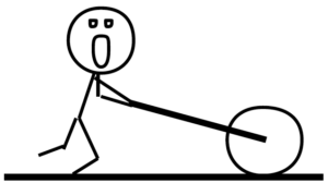 |
Motion Information
| Event 1:
t1 =
r1 = q1 =
v1 = w1 =
a1 = a1 = |
Event 2:
t2 =
r2 = q2 =
v2 = w2 =
a2 = a2 = |
Mathematical Analysis[x]
| The man at right is trapped inside a section of large pipe. If that’s not bad enough, the pipe begins to roll from rest down a 35 m long, 180 incline! The pipe has a diameter of 1.2 m. The pipe (and very dizzy man) reach the bottom of the incline after 6.32 s. | 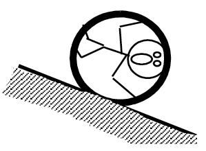 |
Motion Information
| Event 1:
t1 =
r1 = q1 =
v1 = w1 =
a1 = a1 = |
Event 2:
t2 =
r2 = q2 =
v2 = w2 =
a2 = a2 = |
Mathematical Analysis[xi]
| The unlucky man is falling at 20 m/s, 75 m above the crocodile-infested waters below! In an attempt to save him, the brake shoe is pressed against the spinning pulley. The action of the brake shoe gives the pulley an angular acceleration of 7.5 rad/s2. The man is saved! (Barely.) | 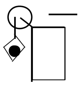 |
Motion Information
| Lucky Man
Event 1:
t1 =
r1 =
v1 =
a1 =
|
Event 2:
t2 =
r2 =
v2 =
a2 =
|
Pulley
Event 1:
t1 =
q1 =
w1 =
a1 = |
Event 2:
t2 =
q2 =
w2 =
a2 = |
Mathematical Analysis[xii]
| The device at right guarantees all the excitement of skiing without the need for hills. The man begins from rest and reaches a speed of 17 m/s after the block falls 10 m. The inner and outer pulley diameters are 0.40 m and 0.90 m, respectively. | 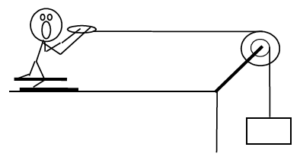 |
Motion Information
| Skier
Event 1:
t1 =
r1 =
v1 =
a1 =
|
Event 2:
t2 =
r2 =
v2 =
a2 =
|
Pulley
Event 1:
t1 =
q1 =
w1 =
a1 = |
Event 2:
t2 =
q2 =
w2 =
a2 = |
Block
Event 1:
t1 =
r1 =
v1 =
a1 =
|
Event 2:
t2 =
r2 =
v2 =
a2 =
|
Mathematical Analysis[xiii]
Tired of walking up the stairs, an engineering student designs an ingenious device for reaching her third floor dorm room. An block is attached to a rope that passes over the outer diameter of a 0.7 m outer diameter, disk-shaped compound pulley. The student holds a second rope, wrapped around the inner 0.35 m diameter of the pulley. When the block is released, the student is pulled up to her dorm room, 8 m off the ground, in 11.2 s.
Motion Information
| Student
Event 1:
t1 =
r1 =
v1 =
a1 =
|
Event 2:
t2 =
r2 =
v2 =
a2 =
|
Pulley
Event 1:
t1 =
q1 =
w1 =
a1 = |
Event 2:
t2 =
q2 =
w2 =
a2 = |
Block
Event 1:
t1 =
r1 =
v1 =
a1 =
|
Event 2:
t2 =
r2 =
v2 =
a2 =
|
Mathematical Analysis[xiv]
| The device at right is used to lift a heavy load. The free rope is attached to a truck that, from rest, accelerates to the right with a constant acceleration. The block is lifted 25 m in 45 s. The inner and outer pulley diameters are 0.40 m and 0.90 m, respectively. |  |
Motion Information
| Truck
Event 1:
t1 =
r1 =
v1 =
a1 =
|
Event 2:
t2 =
r2 =
v2 =
a2 =
|
Pulley
Event 1:
t1 =
q1 =
w1 =
a1 = |
Event 2:
t2 =
q2 =
w2 =
a2 = |
Block
Event 1:
t1 =
r1 =
v1 =
a1 =
|
Event 2:
t2 =
r2 =
v2 =
a2 =
|
Mathematical Analysis[xv]
| The device at right is used to lift a load quickly. The free rope is attached to a truck that, from rest, accelerates to the right with a constant acceleration. The block is lifted 25 m in 15 s. The inner and outer pulley diameters are 0.40 m and 0.90 m, respectively. | 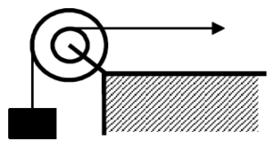 |
Motion Information
| Truck
Event 1:
t1 =
r1 =
v1 =
a1 =
|
Event 2:
t2 =
r2 =
v2 =
a2 =
|
Pulley
Event 1:
t1 =
q1 =
w1 =
a1 = |
Event 2:
t2 =
q2 =
w2 =
a2 = |
Block
Event 1:
t1 =
r1 =
v1 =
a1 =
|
Event 2:
t2 =
r2 =
v2 =
a2 =
|
Mathematical Analysis[xvi]
| The device at right is used to quickly lift the block shown. The free rope is pulled downward at a constant speed of 2 m/s for 15 s. The inner and outer diameters of the big pulley are 0.40 m and 0.90 m, and the inner and outer diameters of the small pulley are 0.2 m and 0.6 m. | 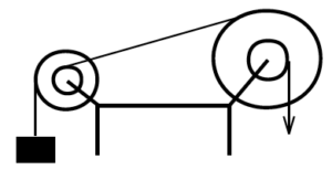 |
Motion Information
| Big Pulley
Event 1:
t1 =
q1 =
w1 =
a1 = |
Event 2:
t2 =
q2 =
w2 =
a2 = |
Little Pulley
Event 1:
t1 =
q1 =
w1 =
a1 = |
Event 2:
t2 =
q2 =
w2 =
a2 = |
Block
Event 1:
t1 =
r1 =
v1 =
a1 =
|
Event 2:
t2 =
r2 =
v2 =
a2 =
|
Mathematical Analysis[xvii]
[i] q2 = 3.53 rad
[ii] t = 0.97 s
[iii] wB2 = 8.98 rad/s
[iv] t = 1.55 s
[v] v1 = 12.3 m/s
[vi] t = 2.39 s
[vii] t2 = 2.8 s
[viii] a = 45.7 rad/s2
[ix] w2 = 35.6 rad/s
[x] a = 0.65 m/s2
[xi] a = 2.92 rad/s2
[xii] t2 = 7.5 s
[xiii] t2 = 2.65 s
[xiv] ablock = 0.256 m/s2
[xv] atruck = 0.056 m/s2
[xvi] atruck = 0.099 m/s2
[xvii] Drblock = 203 m
Homework 10 – Model 4: 15, 17, 20, 23, 25, 27, 36, 39, 41, 42.
Candela Citations
- University Physics I Homework Assignments. Authored by: Mary Mohr. License: CC BY-NC-SA: Attribution-NonCommercial-ShareAlike
- As stated in the text, to describe the general motion of the tire we will break the motion down into a pure translation of the CM and a pure rotation about the CM. Another way to envision the motion is that the tire is rotating about the point on the tire in contact with the ground. The rotation axis of the tire passes through this contact point. (Imagine the point on the tire in contact with the ground as being glued to the ground and the tire rotating about it.) However, an instant later this point is no longer in contact with the ground, and the rotation axis passes through the next point on the tire in contact with the ground. There are advantages and disadvantages to both conceptualizations of the tire’s motion, however, we will restrict ourselves to the view that the tire undergoes pure rotation about the CM. ↵